 Electronics Parts
  Electrical & Automation
  Lab Equipment's
  Power Supply
  Gadgets & Gear
  Miscellaneous
  Services
  Pre-Owned Products





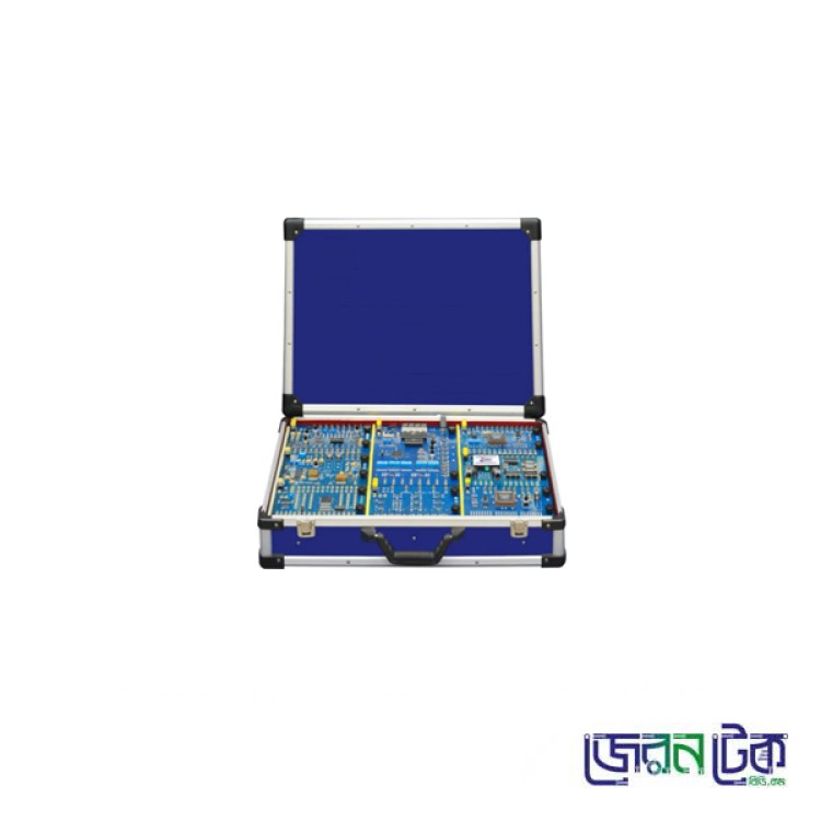
Digital Communication Trainer.
Product Code: LCL004Category: Communication Lab
Brand: ZerOne
Origin: China
Discount: 0% OFF
Availability: Stock Available
Digital Communication Trainer.
Digital Communication Trainer.
OVERVIEWS
(1) The Communication Technology Experimental System adopts the "DSP +
FPGA" development platform, on which multiple communication systems are
implemented, including the digital baseband transmission system, etc.
(2) The communication system is used to integrate 11 technologies in series,
including baseband transmission technology, digital modulation and demodulation
technology, synchronization technology, etc.
(3) It adopts an embedded modular design. All modules feature uniform size,
flexible structure and convenient upgrade. Users can select and configure the
required modules in a building-block manner according to their own needs.
(4) Combination of Software and Hardware, reflecting the Development Trend of
Experimental Teaching: Students use software for simulation to calculate data
or generate waveforms, then conduct physical verification, and finally carry
out hands-on development.
(5) It is protected by an acrylic baffle.
TECHNICAL PARAMETERS
(1)AC/DC Power
Supply Input: AC 220V±10% Output: DC +5V/3A,+12V/1A,-12V/0.5A (2)DDS Analog signal source The
type, frequency, amplitude of the output waveform and the duty cycle of the
square wave of the DDS analog signal source are all adjustable. The
output frequency range of the sine wave is 1Hz ~ 200KHz, and the amplitude
range is 200mV ~ 4V. The
output frequency range of the triangular wave is 1Hz ~ 20KHz, and the
amplitude range is 200mV ~ 4V. The
output frequency range of the sawtooth wave is 1Hz~20KHz, and the amplitude range is
200mV~4V. The
output frequency range of Square Wave A is 1Hz~50KHz, the amplitude range is 200mV~4V, and the duty cycle
remains unchanged at 50%. The
output frequency range of Square Wave B is 1Hz~20KHz, the amplitude range is 200mV~4V, and the duty cycle is
adjustable in 5% steps. Frequency
output accuracy: ≤±5%. (3)Analog signal source Analog
voice source: With voice input and output functions, to be used with a
microphone-equipped headset; Fixed-frequency
sine wave output: 1KHz
sine fundamental wave: peak-to-peak value is 1V±0.3V; 2KHz
sine fundamental wave: amplitude range is adjustable from 200mV to 5V; 192KHz
sine carrier wave: peak-to-peak value is 3.6V±0.3V;384KHz sine carrier wave:
amplitude range is adjustable from 250mV to 5V;
(4)Digital signal source Square
wave duty cycle: 50%; 24.576M:
24.576MHz clock signal; 2048K:
2048KHz square wave output; 64K:
64KHz square wave output; 32K:
32KHz square wave output; 8K:
8KHz square wave output; NRZ:
Outputs 24-bit NRZ code. The code rate is determined by the "Code Rate
Selection" DIP switch, and the code pattern is set via the "NRZ
Code Pattern Selection" DIP switch; BS:
Outputs bit synchronization signal. The square wave frequency can be changed
using the "Code Rate Selection" DIP switch; 2BS:
Outputs square wave with a frequency twice that of the bit synchronization
signal. The frequency can be adjusted via the "Code Rate Selection"
DIP switch; FS:
Outputs frame synchronization signal, which is a narrow pulse. A frame
consists of 24 bits, with a duty cycle of 1/48; PN15:
Outputs m-sequence with N=15. The code rate is determined by the "Code
Rate Selection" DIP switch; PN31:
Outputs m-sequence with N=31. The code rate is determined by the "Code
Rate Selection" DIP switch; PN511:
Outputs m-sequence with N=511. The code rate is determined by the "Code
Rate Selection" DIP switch; (1) Experimental box size: 540mm×380mm×130mm
|
EXPERIMENT ITEM
Tool module (1) Signal Source Module 1)
DDS
Analog signal source 2)
Digital
signal source 3)
Sine
wave fixed-frequency signal source 4)
Analog
voice source Analog
Signal Digitalization and Time Division Multiplex (2) Sampling Theorem (PAM)
Experiment (Analog Signal Digitization Module) (3) Pulse Encoding Modulation and
Demodulation Experiment PCM (Analog Signal Digitization Module) (4) Continuous Variable Slope Delta (CVSD) Modulation
and Demodulation Experiment (Analog Signal Digitization Module) (5) Time Division Multiplexing (TDM) Experiment
(Analog Signal Digitization Module, Multiplexing Module) Common Code Patterns of Base Band Transmission Code Pattern Transformation Experiment (Code
Pattern Transformation Module) Binary Digial Modulation (7)
2ASK Modulation and Demodulation Experiment
(Digital Modulation Module, Digital Demodulation Module) (8) 2FSK Modulation and
Demodulation Experiment (Digital Modulation, Digital Demodulation Module) (9) 2PSK Modulation and
Demodulation Experiment (Digital Modulation, Digital Demodulation Module) (10)
DPSK Modulation and Demodulation Experiment (Digital Modulation, Digital
Demodulation Module) Synchronization (11) Synchronization Carrier
Extraction Experiment (Frequency band Synchronization Extraction Module) (12) Symbol Synchronization
Signal Extraction Experiment (Baseband Synchronization Extraction
Module/Frequency band Synchronization Extraction Module) (13) Frame Synchronization
Signal Extraction Experiment (Baseband Synchronization Extraction
Module/Frequency band Synchronization Extraction Module)
|
Digital Communication Trainer.
OVERVIEWS
(1) The Communication Technology Experimental System adopts the "DSP + FPGA" development platform, on which multiple communication systems are implemented, including the digital baseband transmission system, etc.
(2) The communication system is used to integrate 11 technologies in series, including baseband transmission technology, digital modulation and demodulation technology, synchronization technology, etc.
(3) It adopts an embedded modular design. All modules feature uniform size, flexible structure and convenient upgrade. Users can select and configure the required modules in a building-block manner according to their own needs.
(4) Combination of Software and Hardware, reflecting the Development Trend of Experimental Teaching: Students use software for simulation to calculate data or generate waveforms, then conduct physical verification, and finally carry out hands-on development.
(5) It is protected by an acrylic baffle.
TECHNICAL PARAMETERS(1)AC/DC Power Supply Input: AC 220V±10% Output: DC +5V/3A,+12V/1A,-12V/0.5A (2)DDS Analog signal source The type, frequency, amplitude of the output waveform and the duty cycle of the square wave of the DDS analog signal source are all adjustable. The output frequency range of the sine wave is 1Hz ~ 200KHz, and the amplitude range is 200mV ~ 4V. The output frequency range of the triangular wave is 1Hz ~ 20KHz, and the amplitude range is 200mV ~ 4V. The output frequency range of the sawtooth wave is 1Hz~20KHz, and the amplitude range is 200mV~4V. The output frequency range of Square Wave A is 1Hz~50KHz, the amplitude range is 200mV~4V, and the duty cycle remains unchanged at 50%. The output frequency range of Square Wave B is 1Hz~20KHz, the amplitude range is 200mV~4V, and the duty cycle is adjustable in 5% steps. Frequency output accuracy: ≤±5%. (3)Analog signal source Analog voice source: With voice input and output functions, to be used with a microphone-equipped headset; Fixed-frequency sine wave output: 1KHz sine fundamental wave: peak-to-peak value is 1V±0.3V; 2KHz sine fundamental wave: amplitude range is adjustable from 200mV to 5V; 192KHz sine carrier wave: peak-to-peak value is 3.6V±0.3V;384KHz sine carrier wave: amplitude range is adjustable from 250mV to 5V;
(4)Digital signal source Square wave duty cycle: 50%; 24.576M: 24.576MHz clock signal; 2048K: 2048KHz square wave output; 64K: 64KHz square wave output; 32K: 32KHz square wave output; 8K: 8KHz square wave output; NRZ: Outputs 24-bit NRZ code. The code rate is determined by the "Code Rate Selection" DIP switch, and the code pattern is set via the "NRZ Code Pattern Selection" DIP switch; BS: Outputs bit synchronization signal. The square wave frequency can be changed using the "Code Rate Selection" DIP switch; 2BS: Outputs square wave with a frequency twice that of the bit synchronization signal. The frequency can be adjusted via the "Code Rate Selection" DIP switch; FS: Outputs frame synchronization signal, which is a narrow pulse. A frame consists of 24 bits, with a duty cycle of 1/48; PN15: Outputs m-sequence with N=15. The code rate is determined by the "Code Rate Selection" DIP switch; PN31: Outputs m-sequence with N=31. The code rate is determined by the "Code Rate Selection" DIP switch; PN511: Outputs m-sequence with N=511. The code rate is determined by the "Code Rate Selection" DIP switch; (1) Experimental box size: 540mm×380mm×130mm
| EXPERIMENT ITEMTool module (1) Signal Source Module 1) DDS Analog signal source 2) Digital signal source 3) Sine wave fixed-frequency signal source 4) Analog voice source Analog Signal Digitalization and Time Division Multiplex (2) Sampling Theorem (PAM) Experiment (Analog Signal Digitization Module) (3) Pulse Encoding Modulation and Demodulation Experiment PCM (Analog Signal Digitization Module) (4) Continuous Variable Slope Delta (CVSD) Modulation and Demodulation Experiment (Analog Signal Digitization Module) (5) Time Division Multiplexing (TDM) Experiment (Analog Signal Digitization Module, Multiplexing Module) Common Code Patterns of Base Band Transmission Code Pattern Transformation Experiment (Code Pattern Transformation Module) Binary Digial Modulation (7) 2ASK Modulation and Demodulation Experiment (Digital Modulation Module, Digital Demodulation Module) (8) 2FSK Modulation and Demodulation Experiment (Digital Modulation, Digital Demodulation Module) (9) 2PSK Modulation and Demodulation Experiment (Digital Modulation, Digital Demodulation Module) (10) DPSK Modulation and Demodulation Experiment (Digital Modulation, Digital Demodulation Module) Synchronization (11) Synchronization Carrier Extraction Experiment (Frequency band Synchronization Extraction Module) (12) Symbol Synchronization Signal Extraction Experiment (Baseband Synchronization Extraction Module/Frequency band Synchronization Extraction Module) (13) Frame Synchronization Signal Extraction Experiment (Baseband Synchronization Extraction Module/Frequency band Synchronization Extraction Module)
|
Watch this video it will give you a clear idea about this product.
Related Product